The pain of Routers and Modems
In this 21st century, where everybody is connected to the Internet, routers and modems are the devices that are under a lot of stress. How much stress? a typical ADSL Modem/Wifi AP work 24 hours a day, 365 days a year, since the day of deployment till the day they die (stop working).
I usually am curious enough to check any device by opening it up, if it gives me trouble. So when it comes to a ADSL router-cum-WiFi, the internet being something I am heavily dependent upon, I cannot just let it go. Internet downtime is a big thing! And moreover, every router repaired is lowering the e-waste problem significantly. So people, don't just throw away your Routers and other devices just because they are not working. In most of the cases, the faults are simple to correct. If you are inquisitive and want to learn something about electronics, or already have some experience, open it up and see whats going on.
The routers we get here, having BSNL as my ISP (I reside in India), are of sub par quality. The WiFi Signal range is not enough (not powerful enough) and the parts used inside are of cheap quality to bring down the cost. Capacitors are the classic components that suffer from this problem, as most other components either have low probability of failure (Inductors, Transformer Filter, ICs, Crystals) because they need to be of good quality. These routers, have to run all the time, and if these capacitors inside are sub par, needless to say they have a very limited and short lifetime. How short you ask? I had to change 2 capacitors twice this year. You can also blame it on the temperature here in India, it gets horribly hot during the summers.
Note: A bootloop looks like this: https://www.youtube.com/watch?v=JTfqwUC2QV4
Note: A bootloop looks like this: https://www.youtube.com/watch?v=JTfqwUC2QV4
 |
| My Lowly Router |
 |
| My Lowly Router Opened up |
So here goes my story.
Giving me "The Boot"
The first time my router gave up on me, it would not start up properly. Initiation started, and it would go through the blinking of LEDs (which I would suspect is the checking and initiation of systems present onboard). But then, after initiation, at the time it should be "Booted", it would reboot. Everything Shut down and it started again. The routine would run again, in a loop, but the router would fail to come online, every time. The first thought that came to my mind was, that the software might have gotten corrupted. All software is bound to get corrupted at some point in the life time of the device. But many-a-times, that is not the case, as I found out later.
The problem with a router stuck in bootloop is, that you cannot get into the web interface. No web interface would mean that you cannot "easily" upload any firmware to it. It might be available by Serial Interface of the router, but if you don't have much experience with Microcontrollers, a specialist might have to chime in.
A bootloop looks something like this: https://www.youtube.com/watch?v=JTfqwUC2QV4
A bootloop looks something like this: https://www.youtube.com/watch?v=JTfqwUC2QV4
Hating downtime, but kinda liking it
With the router down, I had enough reason to open it up and check whats inside, just to satisfy my curiosity. To my surprise, I saw a blown up capacitor. Wow. I was just about to pull the trigger on another router, but replacing a part worth 2 bucks would save me from spending 2000 bucks on a new one! AND HEY! did I mention I am helping lower e-waste?
 |
| A Blown Capacitor R.I.P (Courtesy: Wikipedia) |
 |
| A Cluster of Blown Capacitor, called Capacitor Plague. R.I.P friends (Courtesy: Wikipedia) |
I replaced the capacitor the next day, and bam! the router started up fine and I was online in a snap!
Alas I have no evidence of that first repair. I did not have this blog on my mind when I repaired it.
Alas I have no evidence of that first repair. I did not have this blog on my mind when I repaired it.
Capacitor Plague hits again
So the next time a router died on me, I made sure I opened it up to see what was wrong. Guess what? Blown capacitor again. I searched my personal stash of components, and found a cap that was of a higher value (Capacitance) but same voltage rating. Now through my studies, I have seen that resistors and capacitors are used to control the timing of pulses on 555 timers (suggesting they are integral in timing related circuits). So, I was afraid a bit, of ending up with a router that wont work because of different capacitance rating, because the capacitor might have been a part of a timing circuit on the router. But then, I said to myself 'What the heck', I will try it and if it works then good, if not I will get the original value tomorrow and we will be running up again. The capacitor from my stash was bigger than the one that blew up, so the case did not fit properly. Because I am super lazy, I did not go the electronics shack to get the right size -and- rating capacitor. But that worked to my advantage, as you will see later in the story.

Capacitor death is a real problem. I never thought it would affect me in life, we need to make people aware of this issue :)
 |
| Notice the bulges (Not-so-healthy Capacitors) |
 |
| Another angle to see more clearly. |
 |
| New Capacitor that I got. Rated for 85 Degrees, 16V |
 |
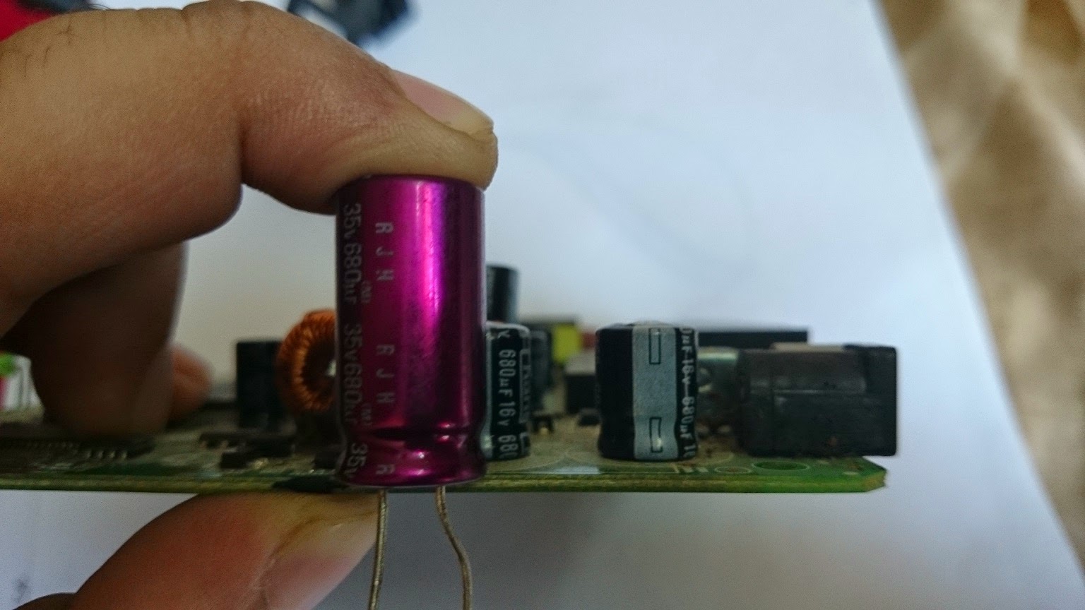
| (Left) I highly doubt the quality of this one (Right) Elna Capacitor rated at 680uF, 35V (hence the height), 105 Degrees C |

Dielectric Strength affects the size of the capacitor, Blue ones are 16V and the bigger one is 35V
 |
| Bad news, It wont fit into the case |
 |
| This one will fit just fine. |
 |
| Capacitors removed Top View |
 |
| Capacitors removed (another angle) |
Soldering the New Capacitors in:
 |
| For a New (not Populated board), doing this would be easy. But here, the holes into which the component leads go are already filled with solder. The picture shows a solution to the problem |
 | ||||
This it to be done one the longer lead appears on this side of the board

Capacitor leads snipped (1 and 2 are power supply capacitors, and 3rd one is unknown module )
|


 |
| All three Capacitors Replaced |
With a router, without any cover, I was able to see first hand how hot the SOCs got. Not just that, touching the capacitors revealed that they were getting hot too.
But Wait, do capacitors heat up?
Through my experiments with capacitors, I had noted, and, was under the impression, that capacitors don't heat up if treated properly. Abuse a capacitor and it will blow up on your face. The one thing a capacitor doesn't like is getting its dielectric limit crossed (Voltage Rating). So was it this voltage rating being crossed? Was this voltage responsible for the damage and killing of innocent capacitors? I checked with a multi-meter, and it read 12.06V on the supply rail. 16V capacitors should be able to handle 12V right? Why the ones in here heated up, is still an unanswered question, for which I will be googling a bit.
Through my experiments with capacitors, I had noted, and, was under the impression, that capacitors don't heat up if treated properly. Abuse a capacitor and it will blow up on your face. The one thing a capacitor doesn't like is getting its dielectric limit crossed (Voltage Rating). So was it this voltage rating being crossed? Was this voltage responsible for the damage and killing of innocent capacitors? I checked with a multi-meter, and it read 12.06V on the supply rail. 16V capacitors should be able to handle 12V right? Why the ones in here heated up, is still an unanswered question, for which I will be googling a bit.
The second reason could be the ambient temperature. This reason, why a capacitor might misbehave and want to blow up, is that its temperature reaches its limit due to outside factors. The capacitors I had were rated for 85 degrees Celsius. So, does the temperature inside the router reach that range? I highly doubt that, and need to get together an Arduino data-logging system to measure the exact temperatures, current and voltage, to eliminate these doubts. That will be the content of another post altogether. Till then we cannot know for sure, but the removed cover allowed me to be able to touch and check if the chips run hot. And they did. Almost all the components would reach temperatures that keeping a finger on the these parts would be an uncomfortable event.
The third reason I found during my adventures was, polarity. Dont put the right polarity on a capacitor (for long or a very short period of time) and it will blow.
The increase of temperature in a capacitor increases the pressure inside it (talking about electrolytic capacitors). These capacitors have electrolytes inside them, and naturally the cans they are inside can only be subjected to so much pressure. I have heated up capacitors on a flame (*Dangerous* DO NOT DO IT AT HOME!! I did it so you wouldn't need to do it!) and they exploded because of this, so it explains why these capacitors blow up at the first place.
If you want to see a capacitor exploding, you can watch [ https://www.youtube.com/watch?v=rr7bPmGTQUk ]
Also check out his other videos, they are hilarious!!
Also, one idea to be noted is, capacitors are electrical components. They develop voltage on their terminals and DC current flows through them for some finite time (Till the capacitor gets fully charged), after this finite time, the capacitor is an open circuit to DC voltage. So naturally they would have a characteristic Wattage and a Limit at it (Power Density). I need to search more on this also. (So take this with a grain of salt) But in the case of ripple voltage, where current is changing polarity at the rate of AC supply, things might be getting tricky. Again, I need to research about this more.
These links explained a bit and solidified some of the concepts for me. For example, the concept that ripple current affects capacitors and when not inside the rated limits of the capacitor, it can blow them up. That is one of the reason you can find ripple characteristics in a capacitor's datasheet.
LINKS:
[ http://www.digikey.com/Web%20Export/Supplier%20Content/CDE_338/PDF/CDE_ThermalModel.pdf?redirected=1
http://electronics.stackexchange.com/questions/16499/hot-capacitors-is-that-a-problem
http://electronics.stackexchange.com/questions/51645/should-electrolytic-capacitors-get-hot
http://en.wikipedia.org/wiki/Capacitor
]
Adding a fan! The router must be like Yeah BABY!!
But whatever the reason is, my current router developed bulged capacitors. So today I decided to fix them. Even though the open case points to the fact that it is not that probable that the blowing up of capacitors is ambient temperature related, it will always help to lower the ambient temperature. So I decided to pull the trigger on modding this router with a fan, and replace the capacitors with quality ones. To my astonishment, I did not find any 680uF 16V/25V capacitors. The only one they had were 680uF 35V, which do not fit the case. So I went for 1000uF 16V ones, keeping my fingers crossed and wishing that the capacitors i am replacing do not have any timing jobs they need to take care of.
But whatever the reason is, my current router developed bulged capacitors. So today I decided to fix them. Even though the open case points to the fact that it is not that probable that the blowing up of capacitors is ambient temperature related, it will always help to lower the ambient temperature. So I decided to pull the trigger on modding this router with a fan, and replace the capacitors with quality ones. To my astonishment, I did not find any 680uF 16V/25V capacitors. The only one they had were 680uF 35V, which do not fit the case. So I went for 1000uF 16V ones, keeping my fingers crossed and wishing that the capacitors i am replacing do not have any timing jobs they need to take care of.
 |
| This is the fan that is to be added to the router. The heatsink is for the SOC |

Fan is rated 12V DC at 1 Watts. Heatsink was for a simple Linear regulator
 |
| Current Consumption of fan, based on rating as it appears on the fan |
NOTE: To be able to add the fan to the router, its current consumption and voltage specs should fall within the range of what can be supplied by the power supply. In my case, looking at the fan, i calculated it will need approximately 0.1A of current, which falls within the rated specs on my router's power supply.

Rating specified on the Router

Power Supply for the Beetel 450TC1
Measuring Power (Overhead) available
As I measured the current consumption, I noticed that running with one LAN port connected and WiFi on, with a file downloading on uTorrent, the router was consuming 0.44 to 0.45 Amperes. With the fan running, the multimeter measured 0.52 Amperes. Well inside the rated limits. I suspect that fully loading (All LAN ports connected, plus a lot of WiFi Clients connected) the router would give me problems with the fan being powered simultaneously. WiFi shouldnt be much of a trouble, because at the time of measuring, a total of 8 devices were connected. I am hoping I will never have to cross the limit. The addition of a switch in series with the fan will help me in such a case. Originally I added the switch in case there was too much noise for my parents to sleep in the room, and in case i get WiFi Reception troubles because of the addition of two current carrying conductors running near the Antenna. It would have been a problem if these wires were to be carrying high frequency data, but a fan doesn't need that.
The motors used in these fans are brushless DC. The rotor has nothing but a magnet mounted on the inside. These motors do not need any brushes, and so this arrangement increases the lifetime of the motor compared to brushed ones, and extra electrical noise wouldnt be introduced into the system. I wish I had an oscilloscope to measure how much noise is introduced onto a power rail comparing brushed and brushless motors. But just to be safe, I chose to put a Capacitor in parallel with the supply to the motor. Being a 680uF 35V one, it should be able to handle any noise that the motor creates, even if it is minimal. Its a design choice, not very scientific, as I needed an oscilloscope to know exactly how much it helped and if the addition even helped or not.

I was lucky enough to find a vent I could create for the wires to be soldered inside the case, onto the jack, and be brought outside the case where the Fan, the Capacitor and the Switch lie. i usually am not that lucky, to be able to get that kind of a fit with such a mod.
 |
| Proposed placement of fan onto the fan |
When I was building my first Raspberry Pi case and getting a Switching regulator to lower a 12V rail voltage to 5V was too expensive, i had to use a linear regulator that could allow atleast 2A of current for the pi. To cool this regulator, as i noted in my experiments that as the regulator heated up, the current output went down, I was forced to put a fan inside the case to keep it cool. It was kind of an overkill, but I learned a lot from that build. It came to my attention that, pushing air through a case is better than sucking it from outside in. that i could notice with the amount of air that was displaced when sucking air inside the case was lower than the amount that could be pushed out.
 |
| Circumference of the Fan |
Same concept to be applied here. But the fan should not be on the top of a part that you want to cool. As, directly under the rotor of the fan there is minimal air-flow. Wanting to cool the whole system, i decided to put the fan closer to the edge. Sucking air in from one side, closing the vents on this side, will force the air over the whole system and effectively cool it (Atleast thats the theory, will need to measure temps to see what actually is happening). But it should help the blowing capacitors. Bringing down the ambient temperature should help. Will get to know the real story during the summers.
I drew onto the case of the router, the shape of the fan, subtracted a little from the lines outside, drew a small square inside and removed it using a heated knife. Then the fan was placed onto the case. I could have fixed it onto the case with screws, but that meant extra work (drilling holes). But since i have a Hot Glue gun, i hot glued the fan onto the newly created vent instead.
 |
| Spreading Thermal Paste onto the heat-sink |
 |
| Heat sink attached to the SOC |
Just placing the heat-sink on top of the chip doesnt cut it. First of all there is nothing to keep it there if you move the router, which is only natural and it would happen. So to make the heat-sink stick and better thermal efficiency, I added a thin coat of thermal paste. Even if its low quality and cheap, i needed it to keep the heat-sink in place.
I ran it once again to see if everything was fine, and once i was sure it is all OK, and I can connect to the internet, I packed the router up.
It makes a little bit of noise, but its nothing I cannot live with. The air it pushes outside is cool, and I have added a little transparent tape to the edge to which the fan lies close to (To force air over the whole board, rather than losing in from this side). Overall, I am happy with the performance as i can feel cool air being pushed outside the system. Again, the real test will be the summers, but I think it will pass the test.
The Placement of the Fan
As one can imagine, the placement of the fan on the body of the router was an important decision. I learned about the placement of a fan on a system that needs cooling from a little bit of practical analysis when i was building a case for my raspberry pi. It was not the raspi that needed cooling as much as the Linear regulator. A linear regulator produces/releases heat into the atmosphere to regulate. The problem with such a system is
1. Not Efficient
2. If efficiency is not a factor, consider that as the temperature of the regulator rises, it loses its current output capabilities.


The circuit with switch and capacitor connected
 Everything glued together
 Everything glued together (2)
 Finished product (back view)
The Placement of the Fan
As one can imagine, the placement of the fan on the body of the router was an important decision. I learned about the placement of a fan on a system that needs cooling from a little bit of practical analysis when i was building a case for my raspberry pi. It was not the raspi that needed cooling as much as the Linear regulator. A linear regulator produces/releases heat into the atmosphere to regulate. The problem with such a system is
1. Not Efficient
2. If efficiency is not a factor, consider that as the temperature of the regulator rises, it loses its current output capabilities.
 |
| Outline drawn to make a vent for the fan |
 |
| Scheme 1, Suck air inside through Router Vents |
 | ||||
| Scheme 2, Force air through Vents sucking from the fan
Why I wasn't buying a system with a Switching regulator? Well, they cost more than simple linear regulators. So i was forced to devise a system where a fan and a linear regulator was cheaper than a Switching regulator. Interesting experiments were those. It went as far as trying to use Wax as a coolant after water with the regulator submerged in it. As my system was not needed to be mobile, i could afford such solutions, but i did not because they were impractical and just experiments. Overall I had a lot of fun working with them.
So the fan vent should be at a place on the body of the device that needs cooling, from where the Air intake flows over most of the board. Then comes the question of whether to create suction so as to push the air through the fan, out of the vents of the device, -or- to pull air inside through the vents and push out through the fan vent.
Well, here is the deal. Air in = Air out. So to maximise air flow we need to maximize air In. The vents on the device are very small, even though large in number. So, the votes goo in the favor of the fan sucking air from the outside, and pushing it through the device's components and out through its vents. That way, because the vent of the fan is bigger and localized (One surface through which air passes in), we can get more amount of air inside and over the components compared to sucking it in through the vents.
This method, ofcourse has a pitfall. More dust will collect on to the board. Only time will tell if it will affect the thermal dissipation of the router in a negative or a positive way.
  

The fan, hot glued to the casing of the router

680uF, 35V Elna, used as a filter capacitor
|


The circuit with switch and capacitor connected
Measurement of current Done with fan on and off
 |
| Booting up, fan running, 0.43A of current |
 |
| Booted up and clients connected 0.49A of current (Fan running) |
 |
| Booted up, fan off, 0.41A of current being consumed |
 |
| Close up of contraption for measurement of current |
 |
My contraption for measurement of Current (Banana replaces banana)
Router running with all its glory
It has been weeks since this mod was performed on the router, and it is working flawless since then. the air it pushes outside of the vents is cool all the time, making me believe that it is providing the cooling effect the mod is designed for. But, to be honest it is winter season and real testing will be done only in the summers.
PS: I am thinking of coming up with a system that can effectively measure the temperature of the components inside, particularly the SOC. Because i have placed a switch, it will allow me to make measurements both with and without the fan. It *might* get to be the content of another post altogether!
Happy hacking, people!
|